battery Ram 1500 2013 Get to Know Guide
[x] Cancel search | Manufacturer: RAM, Model Year: 2013, Model line: 1500, Model: Ram 1500 2013Pages: 196, PDF Size: 9.66 MB
Page 150 of 196

JUMP-STARTING
• If your vehicle has a discharged bat-tery it can be jump-started using a set
of jumper cables and a battery in an-
other vehicle or by using a portable
battery booster pack.
•
Jump-starting can be dangerous if done
improperly so please follow the proce-
dures in this section carefully.
NOTE:
When using a portable battery booster
pack follow the manufacturer’s operating
instructions and precautions.
Preparations for Jump-Start
• The battery in your vehicle is located in the front of the engine compartment, behind the left headlight assembly.
NOTE:
The positive battery post is covered with a protective cap. Lift up on the cap to gain
access to the positive battery post.
• Set the parking brake, shift the automatic transmission into PARK and turn the ignition to OFF.
• Turn off the heater, radio, and all unnecessary electrical accessories.
• If using another vehicle to jump-start the battery, park the vehicle within the jumper cables reach, set the parking brake and make sure the ignition is OFF.
Jump-Starting Procedure
• Connect the positive (+)end of the jumper cable to the positive (+)post of the
discharged vehicle.
• Connect the opposite end of the positive (+)jumper cable to the positive (+)post
of the booster battery.
• Connect the negative end (-)of the jumper cable to the negative (-)post of the
booster battery.
• Connect the opposite end of the negative (-)jumper cable to a good engine ground
(exposed metal part of the discharged vehicle’s engine) away from the battery and
the fuel injection system.
• Start the engine in the vehicle that has the booster battery, let the engine idle a few minutes, and then start the engine in the vehicle with the discharged battery.
WHAT TO DO IN EMERGENCIES
148
Page 151 of 196

Once the engine is started, remove the jumper cables in the reverse sequence:
• Disconnect the negative(-)jumper cable from the engine ground of the vehicle
with the discharged battery.
• Disconnect the negative end (-)of the jumper cable from the negative (-)post of
the booster battery.
• Disconnect the opposite end of the positive (+)jumper cable from the positive (+)
post of the booster battery.
• Disconnect the positive (+)end of the jumper cable from the positive (+)post of
the discharged vehicle.
• If frequent jump-starting is required to start your vehicle you should have the battery and charging system inspected at your authorized dealer.
CAUTION!
• Do not use a portable battery booster pack or any other booster source with a
system voltage greater than 12 Volts or damage to the battery, starter motor,
alternator or electrical system may occur.
• Failure to follow these procedures could result in damage to the charging system of the booster vehicle or the discharged vehicle.
•
Accessories that can be plugged into the vehicle power outlets draw power from
the vehicle’s battery, even when not in use (i.e., cellular phones, etc.). Eventually,
if plugged in long enough, the vehicle’s battery will discharge sufficiently to
degrade battery life and/or prevent the engine from starting.
WARNING!
• When temperatures are below the freezing point, electrolyte in a discharged battery may freeze. Do not attempt jump-starting because the battery could
rupture or explode and cause personal injury. Battery temperature must be
brought above the freezing point before attempting a jump-start.
•
Take care to avoid the radiator cooling fan whenever the hood is raised. It can start
anytime the ignition switch is on. You can be injured by moving fan blades.
• Remove any metal jewelry, such as watch bands or bracelets, that might make an inadvertent electrical contact. You could be severely injured.
• Batteries contain sulfuric acid that can burn your skin or eyes and generate
hydrogen gas which is flammable and explosive. Keep open flames or sparks
away from the battery.
• Do not allow vehicles to touch each other as this could establish a ground
connection and personal injury could result.
• Failure to follow this procedure could result in personal injury or property
damage due to battery explosion.
• Do not connect the cable to the negative post (-) of the discharged battery. The resulting electrical spark could cause the battery to explode and could result in
personal injury.
WHAT TO DO IN EMERGENCIES
149
Page 153 of 196

Center Console Shifter
• Firmly set the parking brake.
•
Turn the Key Fob to the ACC or ON/RUN
position without starting the engine.
• Press and maintain firm pressure on the brake pedal.
• Using a screwdriver, press and hold the override tab through the access
port on the center console.
• Move the shift lever into the NEUTRAL position and start the vehicle.
• Release the parking brake.
MANUAL PARK RELEASE — EIGHT SPEED TRANSMISSION
• In order to push or tow the vehicle in cases where the transmission will not shift out of PARK (such as a dead battery), a Manual Park Release is available.
• Follow these steps to use the Manual Park Release: • Firmly apply the parking brake.
• Using a small screwdriver or similar tool, remove the Manual Park Release
access cover, which is just above the parking brake release handle, below and to
the left of the steering column.
WHAT TO DO IN EMERGENCIES
151
Page 171 of 196

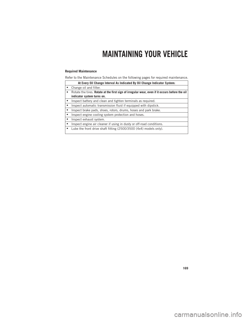
Required Maintenance
Refer to the Maintenance Schedules on the following pages for required maintenance.
At Every Oil Change Interval As Indicated By Oil Change Indicator System:
• Change oil and filter.
• Rotate the tires. Rotate at the first sign of irregular wear, even if it occurs before the oil
indicator system turns on.
• Inspect battery and clean and tighten terminals as required.
• Inspect automatic transmission fluid if equipped with dipstick.
• Inspect brake pads, shoes, rotors, drums, hoses and park brake.
• Inspect engine cooling system protection and hoses.
• Inspect exhaust system.
• Inspect engine air cleaner if using in dusty or off-road conditions.
• Lube the front drive shaft fitting (2500/3500 (4x4) models only).
MAINTAINING YOUR VEHICLE
169
Page 180 of 196

FUSES
POWER DISTRIBUTION CENTER (FUSES)
• The Power Distribution Center is lo-cated in the engine compartment near
the battery. This center contains car-
tridge fuses and mini fuses. A descrip-
tion of each fuse and component may
be stamped on the inside cover, other-
wise the cavity number of each fuse
is stamped on the inside cover that
corresponds to the following chart.
Cavity Cartridge Fuse Micro Fuse Description
F01 80 Amp Red Rad Fan Control Module –
If equipped
F03 60 Amp Yellow Rad Fan – If Equipped
F05 40 Amp Green Compressor for Air Suspension –
If Equipped
F06 40 Amp Green Antilock Brakes/Electronic
Stability Control Pump
F07 40 Amp Green Starter Solenoid
F08 30 Amp Pink Emissions Diesel – If Equipped
F09 40 Amp Green Diesel Fuel Heater – If Equipped
F10 40 Amp Green Body Controller / Exterior
Lighting #2
F10 50 Amp Red Body Controller / Exterior Lighting
#2 – If Equipped with Stop/Start
F11 30 Amp Pink Integrated Trailer Brake Module –
If Equipped
F12 40 Amp Green Body Controller #3 / Interior
Lights
F13 40 Amp Green Blower Motor
F14 40 Amp Green Body Controller #4 / Power Locks
F15 30 Amp Pink Electric Park Brake Right Side –
If Equipped
F19 30 Amp Pink SCR – If Equipped
F20 30 Amp Pink Passenger Door Module
F21 30 Amp Pink Drive Train Control Module
F22 20 Amp Yellow Engine Control Module
F23 30 Amp Pink Body Controller #1
F24 30 Amp Pink Driver Door Module
F25 30 Amp Pink Front Wiper Low Speed
MAINTAINING YOUR VEHICLE
178
Page 181 of 196

Cavity Cartridge Fuse Micro FuseDescription
F25 30 Amp Pink Front Wiper High Speed
F26 30 Amp Pink Antilock Brakes/Stability Control
Module/Valves
F28 20 Amp Yellow Trailer Tow Backup Lights –
If Equipped
F29 20 Amp Yellow Trailer Tow Parking Lights –
If Equipped
F30 30 Amp Pink Trailer Tow Receptacle
F32 30 Amp Pink Drive Train Control Module –
If Equipped
F33 20 Amp Yellow Diesel Fuel Heater #1 –
If Equipped / Rear Blower – If Equipped
F34 30 Amp Pink Vehicle System Interface
Module #2 – If Equipped
F35 30 Amp Pink Sunroof – If Equipped
F36 30 Amp Pink Rear Defroster– If Equipped
F37 30 Amp Pink Diesel Fuel Heater #2 if equipped
F38 30 Amp Pink Power Inverter 115V AC –
If Equipped
F39 30 Amp Pink Vehicle System Interface
Module #1– If Equipped
F41 10 Amp RedActive Grill Shutter
F42 20 Amp Yellow Horn
F43 10 Amp Red Snow Plow (Left) – If Equipped
F44 10 Amp RedDiagnostic Port
F46 10 Amp Red Tire Pressure Monitor
F47 10 Amp Red Snow Plow (Right) – If Equipped
F49 10 Amp Red Instrument Panel Cluster
F50 20 Amp Yellow Air Suspension Control Module –
If Equipped
F51 10 Amp Red Ignition Node Module / Keyless
Ignition
F52 5 Amp TanBattery Sensor
F53 20 Amp Yellow Trailer Tow – Left Turn/Stop Lights
F54 20 Amp Yellow Adjustable Pedals
F55 20 Amp Yellow E38 Radio – If Equipped
F56 15 Amp Blue Additional Diesel Content –
If Equipped
F57 20 Amp YellowTransmission
MAINTAINING YOUR VEHICLE
179
Page 189 of 196

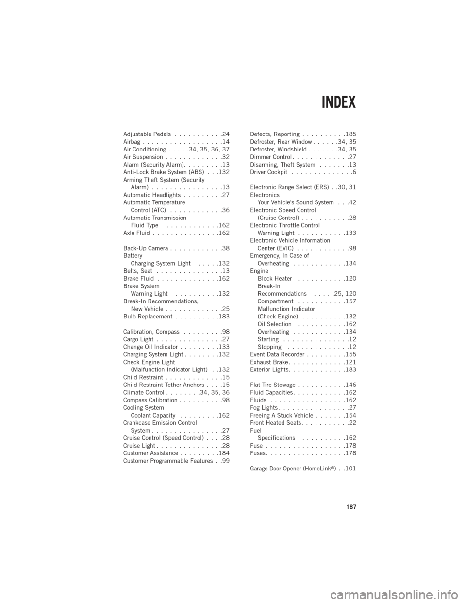
AdjustablePedals ...........24
Airbag..................14
Air Conditioning.....34,35,36,37
Air Suspension .............32
Alarm (Security Alarm) .........13
Anti-Lock Brake System (ABS) . . .132
Arming Theft System (Security Alarm) ................13
Automatic Headlights .........27
Automatic Temperature Control (ATC) ............36
Automatic Transmission FluidType ............162
AxleFluid...............162
Back-Up Camera ............38
Battery Charging System Light .....132
Belts, Seat ...............13
Brake Fluid ..............162
Brake System WarningLight ..........132
Break-In Recommendations, New Vehicle .............25
BulbReplacement ..........183
Calibration,Compass .........98
CargoLight...............27
ChangeOilIndicator.........133
Charging System Light ........132
Check Engine Light (Malfunction Indicator Light) . .132
Child Restraint .............15
Child Restraint Tether Anchors ....15
Climate Control ........34,35,36
Compass Calibration ..........98
Cooling System Coolant Capacity .........162
Crankcase Emission Control System ................27
Cruise Control (Speed Control) ....28
CruiseLight...............28
Customer Assistance .........184
Customer Programmable Features . .99 Defects, Reporting
..........185
Defroster, Rear Window ......34,35
Defroster, Windshield .......34,35
DimmerControl.............27
Disarming, Theft System .......13
Driver Cockpit ..............6
Electronic Range Select (ERS). .30, 31
Electronics Your Vehicle's Sound System . . .42
Electronic Speed Control (Cruise Control) ...........28
Electronic Throttle Control WarningLight ...........133
Electronic Vehicle Information Center (EVIC) ............98
Emergency, In Case of Overheating ............134
Engine BlockHeater ...........120
Break-In
Recommendations .....25,120
Compartment ...........157
Malfunction Indicator
(CheckEngine) ..........132
Oil Selection ...........162
Overheating ............134
Starting ...............12
Stopping ..............12
Event Data Recorder .........155
Exhaust Brake .............121
Exterior Lights .............183
FlatTireStowage...........146
Fluid Capacities ............162
Fluids .................162
FogLights................27
Freeing A Stuck Vehicle .......154
Front Heated Seats ...........22
Fuel Specifications ..........162
Fuse ..................178
Fuses..................178
Garage Door Opener (HomeLink®). .101
INDEX
187